Boolean Algebra
- Categories Boolean Algebra, Computer Hardware
We all have studied algebra in maths where we had expressions containing variables and constants which we solve using some rules. Boolean Algebra is a branch of algebra where values of variables are True or False or just yes or No. It is also called logic or Boolean decision or Binary Value quantity. Here 1 means True and 0 means False Or 1 is yes and 0 is No.
It was named after George Boole who discovered a link between Mathematics and logic in the year 1854.

Its most important application is in running computers and electronic machines as is an important tool in analyzing, designing and implementing digital circuits or integrated circuits. At basic level circuits are made from Logic Gates
Logic gate is an integrated circuit which operates on one or more signals and produce single output. Gates are digital circuits because the input and output signals are denoted by either 1(high voltage) or 0 (low voltage)
Coming back to Boolean Algebra, it is made up of
- Elements -which are variables or constants with value of 1 or 0. Since they store only 2 values they are also called logical variables or binary valued variable.
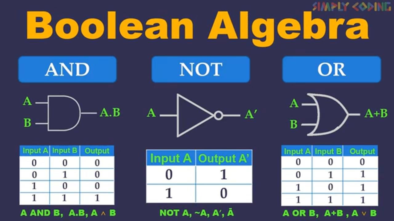
- Logical Operators -which are And, Or and Not
- Axioms and Theorems such as De Morgans Theorem, Duality theorem etc.
These elements and operators form Boolean Algebra Expressions which are solved using various Axioms and Theorems.
To prove if expressions are equal or test if theorems are valid, many times we use Truth Tables.
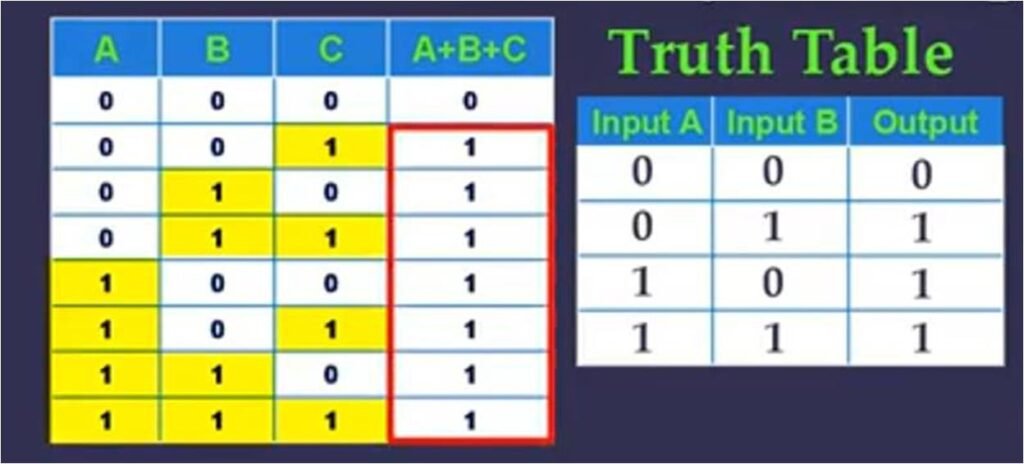
Truth Table is tabular structure which shows all the possible input value used and output produced by applying the logical operators. So if you have one variable, it will have 2 possible values 0 and 1 or True and False. If you have 2 variables it will have 4 possible combination of 0 and 1 as shown. And if you have 3 variables then it will have 8 possible combination of 0 and 1 so if you have n variables then you will have 2 raise to the power of n combination of input value values. Here if you look closely, the combinations are written in set order which is nothing but binary number of 0,1,2,3 and so on.

We will now learn about basic Logical Operators, NOT, OR and AND which are applied on these elements or variables to obtain the result or output.
Logical NOT Operator
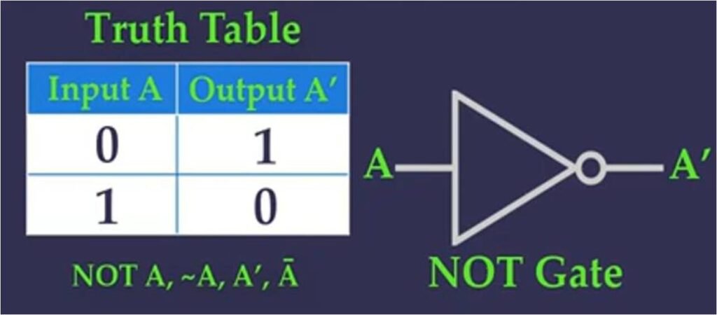
This operator is also called as Invertor, Complement or Negation Operator. This operator takes in one single input and gives one output which is opposite of it.
So if you have input variable A with value 0 it converts input of 0’s into 1’s and if it is 1’s into 0’s.
It is denoted by NOT or negation sign or ~ (‘) or ( ) bar.
Since this table gives all possible values of Input and is output, this is the truth table for NOT Operator.
Real life Example of NOT gate is that of the car door is not closed the alarm light will go on and vice versa
In digital circuits it is called as Not Gate and is depicted as shown.
- It takes only one input signal and produce only one output signal
- The output of NOT gate is complement of its input.
- It is also called inverter as it inverts the input signal.
Logical OR operator
It is also called as Disjunction operator. The operator results in logical addition of the binary valued quantities.
So if you have 2 input values and we take all different combination of inputs, the output will be 1 if any of the inputs is 1. So all are 1 except the first row which is 0. This is the truth table for 2 input OR operator. If you have 3 inputs then also it works the same way, we will take all possible combination of Inputs and it will be one if any of the inputs is 1. So leaving first row, all other rows are 2. This is the truth table for 3 input OR
It is denoted by a OR or plus( +) sign or V sign.
Real life example of OR gate is that Doorbell will ring if the front doorbell is pressed or back doorbell is pressed
In digital circuits it is called OR Gate and has the symbol as shown. It gives a high output(1) if one or more of its inputs are high.OR gate also takes two or more input signals and produce only one output signal

Logical AND operator
It is also called as Conjunction operator. This operator results in logical multiplication of two or more binary valued quantities.
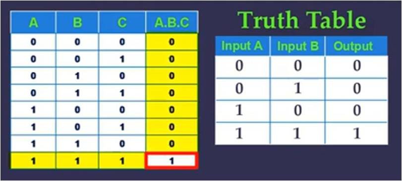
So if you have 2 input values and we take all different combination of inputs, the output will be 1 only if all the inputs are 1. Which is there in only this last row so only last row is 1 and remaining are 0. This is the truth table for 2 input AND operator. If you have 3 inputs then also it works the same way, we will take all possible combination of Inputs and it will be one only when all inputs are 1 which is only this last row. All other rows are 0. This is the truth table for 2 input AND
It is denoted by a AND or dot( .) sign or inverted V sign.
If you take a truth table with three inputs you will see similar output. Only when all 3 inputs are 1 the output is 1, in all other cases the output is 0.
Real life example of AND operator is that Microwave will only start if the start button is pressed and the door is closed
In digital circuits it is called AND Gate and it has symbol as shown. It is an electronic circuit that gives high output(1) only if all its inputs are high.
Questions
We will see now typical questions that are asked on truth tables and logic gates.
On truth table the typical questions are either to draw a truth table for a Boolean expression or using Truth table prove that Boolean expression is true. We will see how you can solve these.
Draw a Truth Table for Boolean Expression
Lets take an expression A’ + (AB’ + C)‘ and see how we can draw a truth table for it.
First thing we will check is that if it is a 2 term or three term expression. We have to first setup all the combination of input values of the term. We learn earlier that if it is two input we write binary numbers from 0 to 3 and if it is 3 term we write binary numbers from 0-7. Since this is 3 term, we will use binary numbers from 0 – 7. These are the three input values. Now to solve this we use the standard BODMAS which we use in the algebra. We first solve for NOT used for individual Input terms. Like here there is NOT A and NOT B. This NOT is for entire sub expression so this we will solve only after solving the expression. For NOT A we will take A column and just reverse it. Similarly for NOT B, we will take B column and reverse it. Next we will solve the expression inside the bracket. We will first solve A.B’ We know this is AND so it will be 1 only when both input is 1 We take the A column and B’ column. So in these only in these 2 places both input is 1 so output will be 1 and remaining all will be 0. Next we will solve AB’ + C. Here we know the output will be 1 if any of the input is 1.So here we take the C column and AB’ column. Here these all are 1s and remaining are 0. Now we will find NOT of this expression which will just be reverse, 0 becomes 1 and 1 becomes 0. Now we need to add this to A’. We have already calculated A’ so we just take that column to add it here. So if any of the input is 1 the output is 1 so These all will have output of 1 and remaining 0. This is the answer for this expression.

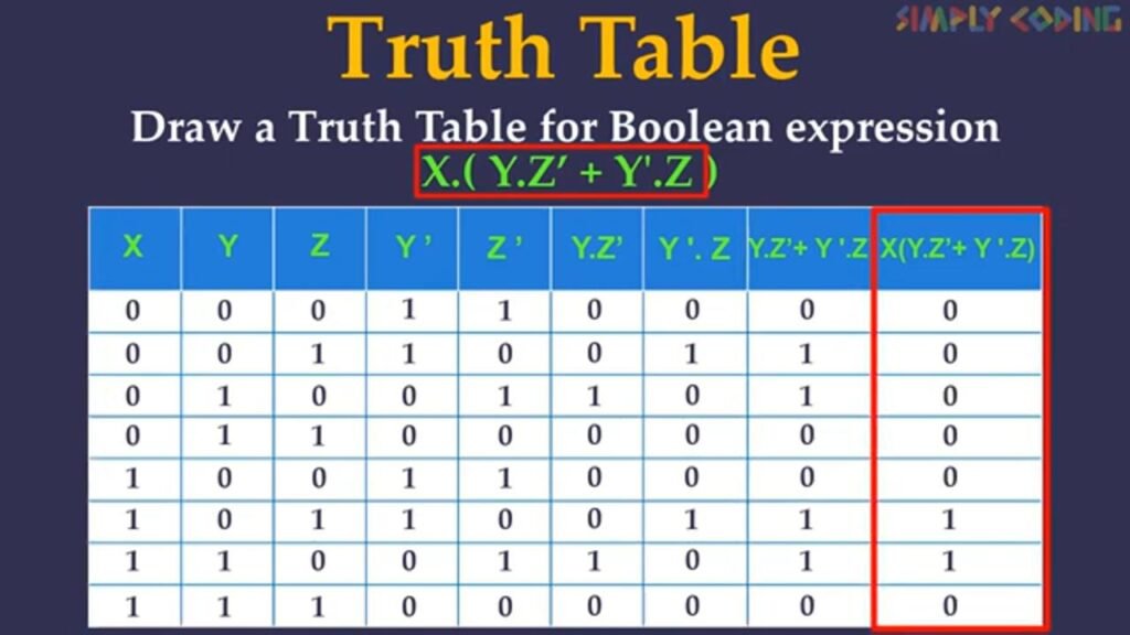
Lets solve another one, draw truth table for X.(Y.Z’ + Y’.Z)
Since this is 3 term, we will first setup combination of input values which are binary numbers from 0 – 7. We will use the standard BODMAS principals of algebra. We first solve for NOT used for individual Input terms. Here there is NOT Y and NOT Z. So we will first Take Y column and negate it and take Z column and complement it.. Next we will solve the expression inside the bracket. We will first solve Y.Z’ We will take Y and Z’ column. We know this is AND so it will be 1 only when both input is 1 So in the table only in these places both input is 1 so output will be 1 and remaining all will be 0. Next we will solve Y’.Z the same way we have solved Y.Z’. We will take the columns of Y’ and Z and apply AND to the values. Only where both input are 1, output is 1 remaining are 0. Next we will solve X.Z’ + Y’Z. We take both the columns and since here it is OR we know the output will be 1 if any of the input is 1. So here these all are 1s and remaining are 0. Now we need to AND this to X. So we will take X and this column and do AND. Only if both input is 1 the output is 1 so These all will have output of 1 and remaining 0. This is the answer for this expression.
Prove a theorem using Truth Tables
Now we will solve some questions where you are asked to prove a theorem or an expression.
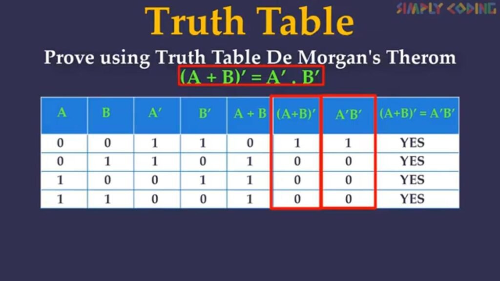
Like prove using Truth table, De Morgan’s Theorem (A +B)’ = A’.B’
Here we solve left hand side of the equation and right hand side of equation and if the output values of both columns are same we say that the theorem is proved. Lets solve this.
Here we see it is two term expression so we will setup all combination of input for these two terms by writing 0-3 in binary. Next we solve for NOT which require only one term so we select the column A and complement it to get A’ and take column B and complement it to get B’. Next we will solve the bracket which is A+B. We take column A and B. Since it is OR or Addition, output will be 1 where any of the input value is 1. So these all values are 1 and remaining are 0. Next we have to find complement of it so we will just reverse the values. So we have the LHS values solved. Next is to get the RHS Values which is A’.B’. We select the A’ column and B’ column and AND it. Output is 1 only where both values are 1 so only these rows are 1 and remaining all are 0. Now we just compare the LHS column with RHS Column, we find all are equal so the theorem is proved.
Solve problems on drawing Logical Gates
Now we will see how to draw logic gates. You could be given an expression and then asked to draw logic circuit gate for it.
Lets start with draw logic gate for A’ + (AB’ + C)’

We solve the logic gatesproblem by first seeing whether it is 2 term or 3 term input, Here it is 3 term so we will just draw three lines on the left for 3 input fields. We use the same BODMAS principals to solve this too. We first look for where NOT terms are used. Here we are using A’ and B’ so we take input from A and B, setup NOT gates and set them up also as vertical lines. Next we will solve the sub equation in brackets. First we will solve AB’ Now we will draw horizontal lines and take input from A and B’ and put AND gate over here. We then take the output from this gate and input from C and use OR gate. Next we apply the NOT Gate on the output of AB’ + C. Last this is added to A’ so we take this and input from A’ and apply OR gate. This is the final result.
Do note some specific points we have used while drawing the gates. The input fields we have drawn vertically including the NOT of individual input terms. Then we take in input from these fields and solve the remaining equation horizontally step by step using the similar BODMAS principles you use in algebra. For the horizontal lines, do remember to put a bigger dot when you are taking input so that there is no confusion as to from where the input is drawn.
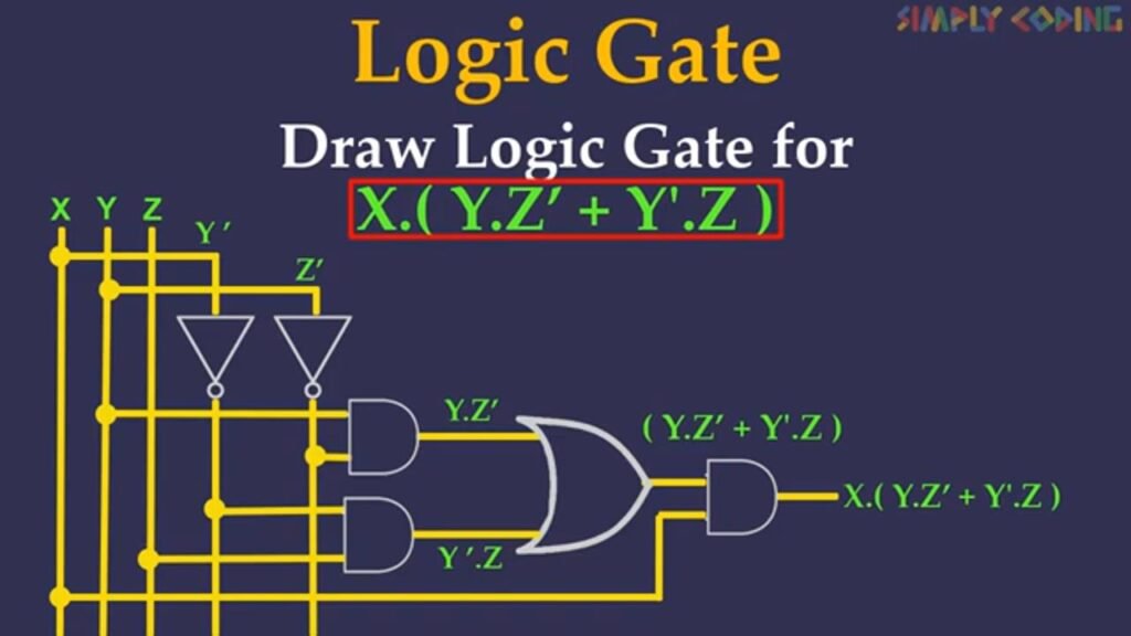
Lets take another question here we will draw logic gate diagram for X.(Y.Z’ + Y’.Z)
We again solve the logic gates problem by first seeing whether it is 2 term or 3 term input, Here it is 3 term so we will just draw three lines on the left for 3 input fields. We use the same BODMAS principals to solve this too. We first look for where NOT terms are used. Here we are using Z’ and Y’ so we take input from Y and Z, setup NOT gates and set them up also as vertical lines. Next we will solve the sub equation in brackets. First we will solve YZ’ Now we will draw horizontal lines and take input from Y and Z’ and put AND gate over here. Next we will solve Y’Z Now we will draw horizontal lines and take input from Y’ and Z and put AND gate over here
We then take the output from this gate and from YZ’ and use OR gate. Next we will take input from YZ’ and Y’Z and apply OR gate. Now this sub expression we will and with X by taking input from X and applying AND gate. This is the final result
